Default Remote
Arduino code to go with the default original remote of the IR Remote Creator App.
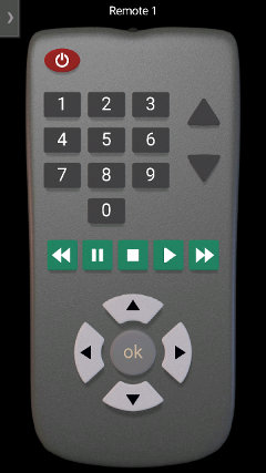
IR Remote
The default remote has 23 buttons, all of which have been set to use the NEC InfraRed protocol.
Default Remote
If you have deleted the remote from the app, you can get it again in one of these ways:
1) If you are accessing this page from a device with the app installed, then tap here to load it into the App.
2) Alternatively download default.txt into the keuwlsoft/ir-remotes/ directory in the documents folder on your Android device, and then load it from within the app.
3) Alternatively, in the load from web link option within the app, enter: https://www.keuwl.com/ir-remotes/default.txt
4) In the App settings, Reset defaults with the restore original remotes option checked (although this method will delete any other remotes currently loaded into the app).
NEC Protocol
This is a popular InfraRed protocol that has some nice built in error checking. It uses pulse distance modulation on a carrier wave that is typically 38 kHz. The distance between pulses is used to differentiate a 0 or 1.
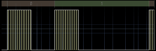
Pulse Distance Modulation
The IR pattern comprises a header pulse, 32 bits of information, and then a stop or end bit. The 32 bits of data are split into an address and a command.
The address decides the target device of the IR transmission whilst the command determines the function on that device.
Both the command and address are sent twice, first as it is, and then as a one's compliment (i.e. inverted) version. For example if the address is 01100111, then the inverted address, address' is 10011000. If the transmitted data hasn't been corrupted, then the logical bitwise AND of the address and address' will yield zero. Likewise for the bitwise AND of command and command'.
For all buttons, the address being used for this demo project is zero. If changing the address of the sent data, make sure the Arduino code is adjusted to match. For example, If you have multiple IR projects, you can assign them different addresses so that the signal is only received by the one that should receive it.
For the buttons, we have used command numbers 0 to 22 (0x00 to 0x16 hex). Thus the code table for the remote is:
| Button | Address | Command |
| 0 | 0x00 | 0x00 |
| 1 | 0x00 | 0x01 |
| 2 | 0x00 | 0x02 |
| 3 | 0x00 | 0x03 |
| 4 | 0x00 | 0x04 |
| 5 | 0x00 | 0x05 |
| 6 | 0x00 | 0x06 |
| 7 | 0x00 | 0x07 |
| 8 | 0x00 | 0x08 |
| 9 | 0x00 | 0x09 |
| On/Off | 0x00 | 0x0A |
| Up Triangle | 0x00 | 0x0B |
| Down Triangle | 0x00 | 0x0C |
| Rewind | 0x00 | 0x0D |
| Pause | 0x00 | 0x0E |
| Stop | 0x00 | 0x0F |
| Play | 0x00 | 0x10 |
| Forward | 0x00 | 0x11 |
| Up | 0x00 | 0x12 |
| Down | 0x00 | 0x13 |
| Left | 0x00 | 0x14 |
| Right | 0x00 | 0x15 |
| Ok | 0x00 | 0x16 |
There is nothing special about this choice of command numbers. Change them if required and update the Arduino code to match.
IR Receiver Module
This project used a VS1838B InfraRed Receiver Module. There are a range of IR receiver modules available, the main difference being in the carrier frequency. 38 kHz is by far the most popular frequency for IR remotes, but you will also find 30 kHz, 33 kHz, 36 kHz 40 kHz, 56 kHz and others available. Unless you need a specific frequency to match a particular remote/device, 38 kHz is probably going to be the cheapest and best option. There is some overlap in frequency capability. i.e. expect a 38 kHz receiver to also be able to pick up a 36 kHz signal (for example), but weaker and at a closer range.
Check the datasheet of your IR receiver module so that you connect you device correctly (otherwise it might heat up and burn out and then not work anymore). The IR receivers generally will have three connections: Ground, +V and a Output. Note that the output could be inverted to what you think it is going to be. Checking the data sheet that the IR receiver uses a suitable voltage for your Arduino to supply is probably a good idea too.
The IR receiver packages do all the necessary amplification & demodulation and just output any IR pattern they receive as a digital signal which we will read with the Arduino.
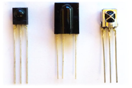
Some IR Receiver Modules (TSOP4838, TSOP31256 and VS1838B).
Components used
- Arduino Uno
- VS1838B InfraRed Receiver Module
Circuit Diagram
Connect the InfraRed Receiver Module to the Arduino as in the circuit diagram below. The output of the receiver module needs to go to pin 2 or 3 of the Arduino as we can enable external interrupts for those pins.
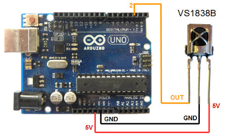
Whilst we are using an Arduino Uno for this demo, you could use a different model if you prefer, just make sure the ir receiver module output is to an external interrupt pin.
The VS1838B InfraRed Receiver Module has 3 connections, GND, 5V, and OUT. For other Receiver Modules, see datasheet to get the correct connections etc.
Arduino code
Open the Arduino software, select the correct COM Port and Arduino device in the Tools menu, copy and paste the sketch below and click upload.
Of note in this sketch is the way it handles the incomming IR pattern data. Rather than tieing up the main loop with PulseIn() commands and constantly monitoring the IR signal, we have used interrupts instead. This leaves the main loop free to carry out other important tasks.
The interrupt is called every time the external interrupt pin changes state. It logs the elapsed micros() time of the Arduino, and then resumes from where it was before. Once IR pattern data has been collected and a pause is observed at the end of the pattern, it's analysis is done in the main loop.
Once new IR command has been received, a switch-case is used to run code for that command. Except, this is just the template, so commands wont do anything unless you add some code.
// Code template for default remote in keuwlsoft's IR remote Creator App
// By keuwlsoft:  www.keuwl.com  24th Feb 2019
// cc Attribution-ShareAlike
//
// This sketch will receive an IR Pattern, Decode the Address and Command (NEC Protocol).
// Then if data valid and address matches, will use a switch case to action the command.
// Does nothing, unless code is added to the switch-case for the buttons you want to use.
// An Interrupt is used to gather the IR Pattern timing, which is later analysed, thus keeping the main loop free for other tasks.
// The Remote and explanation can be found at www.keuwl.com/electronics/rduino/ir/03-default-remote/

int ir_pin=2; //use pins 2 or 3 for external interupts, connect the IR receiver module output here.

long no_change_time=10000; //No change in IR pin for this duration (microseconds) will mark the end of pattern.
const int array_size=100; //Max times to log.  If array is full, it will report the pattern to that point.
long t_array[array_size]; //Array of times of when the IR pin changes state.
int count=0; // Number of times logged to array.
boolean log_micros=true;  //Flag to indicate if able to log times to array
long last_micros=0; //previous array time entry

int addr=0; //Device address decoded from IR pattern
int cmmd=0; //Command decoded from IR pattern
int our_device_addr=0; //integer (0-255) that is an address to identify our device amoungst other devices.
boolean new_data=false; //Flag that is set everytime a new IR command is received


void setup() {
  pinMode(ir_pin, INPUT);

  //attach an interupt to log when the IR pin changes state
  attachInterrupt(digitalPinToInterrupt(ir_pin),interupt,CHANGE);
}

void loop() {

//=========================================== Extract IR Command
  if (count>0){
    if (!log_micros|((micros()-last_micros)>no_change_time)){
      log_micros=false; //make sure array not modified while we analyse it
      //Get Pattern
      count--;
      for (int i=0;i<count;i++){
        t_array[i]=t_array[i+1]-t_array[i];
      }
      //Extract Command And Address of NEC protocol
      if (count>=64){ //Check patten long enough for 32 bits of data
        int pos=count;
        // Extract Command Compliment
        int cmmd2=0x00;
        for (int i=0;i<8;i++){
          cmmd2=cmmd2<<1; pos-=2;
           if (t_array[pos]>1000)cmmd2=cmmd2|1;
        }
        // Extract Command
        cmmd=0x00;
        for (int i=0;i<8;i++){
          cmmd=cmmd<<1; pos-=2;
          if (t_array[pos]>1000)cmmd=cmmd|1;
        }
        //Extract Address Complement
        int addr2=0x00;
        for (int i=0;i<8;i++){
          addr2=addr2<<1; pos-=2;
          if (t_array[pos]>1000)addr2=addr2|1;
        }
        //Extract Address
        addr=0x00;
        for (int i=0;i<8;i++){
          addr=addr<<1; pos-=2;
          if (t_array[pos]>1000)addr=addr|1;
        }

        //check if data was for our device and is valid
        if ((addr2&addr)==0&&(addr2&addr)==0){
          if (addr==our_device_addr) new_data=true;
        }
      }

    log_micros=true; count=0; //Reset array so another IR pattern can be received
    }
  }
//===========================================


//=========== Do Something with the Newly Received Command
  if (new_data){
    switch(cmmd){
      case 0:
        //<-- Insert Code for button '0' press here
      break;
      case 1:
        //<-- Insert Code for button '1' press here
      break;
      case 2:
        //<-- Insert Code for button '2' press here
      break;
      case 3:
        //<-- Insert Code for button '3' press here
      break;
      case 4:
        //<-- Insert Code for button '4' press here
      break;
      case 5:
        //<-- Insert Code for button '5' press here
      break;
      case 6:
        //<-- Insert Code for button '6' press here
      break;
      case 7:
        //<-- Insert Code for button '7' press here
      break;
      case 8:
        //<-- Insert Code for button '8' press here
      break;
      case 9:
        //<-- Insert Code for button '9' press here
      break;
      case 10:
        //<-- Insert Code for On/Off button press here
      break;
      case 11:
        //<-- Insert Code for up triangle button press here
      break;
      case 12:
        //<-- Insert Code for down triangle button press here
      break;
      case 13:
        //<-- Insert Code for Rewind button press here
      break;
      case 14:
        //<-- Insert Code for Pause button press here
      break;
      case 15:
        //<-- Insert Code for Stop button press here
      break;
      case 16:
        //<-- Insert Code for Play button press here
      break;
      case 17:
        //<-- Insert Code for Forward button press here
      break;
      case 18:
        //<-- Insert Code for Up button press here
      break;
      case 19:
        //<-- Insert Code for Down button press here
      break;
      case 20:
        //<-- Insert Code for Left button press here
      break;
      case 21:
        //<-- Insert Code for Right button press here
      break;
      case 22:
        //<-- Insert Code for Ok button press here
      break;

      default:
      break;
    }
    new_data=false;
  }
//===========


  delay(10);
}


//========================================================
// Interupt to log each time the IR signal changes state
void interupt(){
  if (log_micros){
    long m=micros();
    if (count>0&&(m-last_micros)>no_change_time){
      log_micros=false;
    }else{
       t_array[count]=m;
       count++;
       last_micros=m;
       if (count>=array_size) log_micros=false;
     }
  }
}
//========================================================