LED Brightness
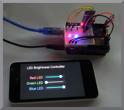
This panel has 3 sliders to control the brightness of 3 LEDs.
This panel demonstrates the slider elements and Pulse Width Modulation (PWM) for controlling
LED brightness.
About this demo
This demo uses the Bluetooth HC-05 or HC-06 modules with an Arduino to communicate to an Android device with Bluetooth. The Bluetooth Electronics app is used with 3 sliders to control the amount of red, green and blue from the LED(s).
Pulse Width Modulation (PWM) is all about turning a digital output on and off rapidly such that information can be encoded in the signal. The average on time of this signal can be used to control the power output to a device, such as the LEDs in this demo. The Arduino analogueWrite() command uses PWM to achieve this. For every 256 counts, the output is held high until the requested analogue write value is reached. This is repeated every 2.04 ms or at 490 Hz (for the 16 MHz Arduino Uno with default settings). Thus a value of 0 will be off all the time, a value of 255 will be on all the time and anything in between will be pulse width modulated to be on for a part of the time.
Note that there are multiple ways of achieving an on state for e.g. 50 % of the time. Like the Arduino, it could be treated like a duty cycle with the first 50% of the counts set as on. However it could also be achieved by splitting the 'on' states such that the state is alternated each clock, … and so on.
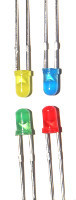
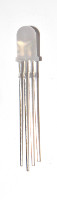
Whilst we have used 3 LEDs and used a 470 Ω resistor (resistance to use depends on LED) in series with them, a single RGB led could also be used. A RGB LED has 4 leads, the longest being the common, and the other three for the red blue and green. Consult the data sheet for which lead corresponds to which colour and for what the current rating is for each colour.
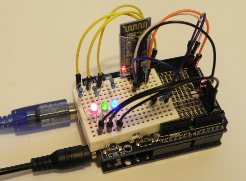
LED Brightness demo build with 3 LEDs
Components used
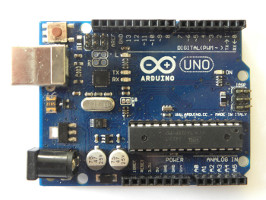
- Arduino Uno
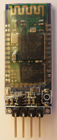
- HC-06 Bluetooth Module
- 3 LEDs or a single RGB LED
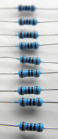
- 470 Ω (depends on LED), 10k and 20k Resistors
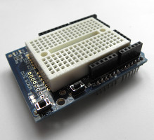
- Prototype Shield for Arduino Uno
Circuit Diagram
Resistors R1, R2 and R3 depend on the LED used. They limit the current so the LED doesn't burn out.
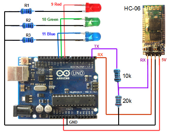
Whilst we are using an Arduino Uno for this demo, although you could use a different model if you prefer, just make sure it has 3 pins with Pulse Width Modulation (PWM) capability and and that the connected pins correspond to that in the Arduino sketch. For this demo we use pins 9, 10 and 11 of the Arduino Uno, setting them as outputs and then use the analogueWrite() command to set the duty cycle.
The Bluetooth module has 4 connections, GND, 5V, RX and TX. The TX pin on the Bluetooth module connects to the RX pin on the Arduino and visa versa. For serial communication, a transmit (TX) connection need to be received by a (RX) connection.
Note that the Bluetooth module operates at 3.3V. Supplying a 5V to the Bluetooth RX pin could damage it, such that a voltage divider should be used to supply a 3.3V signal to the RX pin. This is achieved in this demo with 20k and 10k resistors. The TX pin of the Bluetooth module does not need modification and can connect directly to the Arduino RX pin. This is because the HIGH on 3.3V logic will still be recognised as a HIGH on the 5V logic circuitry on the Arduino.
Arduino code
//PWM LED Brightness and Bluetooth Serial Link Demo
//By keuwlsoft:  www.keuwl.com  23rd Aug 2015

int Red_LED_Pin = 9; // PWM Pin for Red LED
int Green_LED_Pin = 10; // PWM Pin for Green LED
int Blue_LED_Pin = 11; // PWM Pin for Blue LED

//Varibles to hold brightness values ranging from 0 (off) to 255 (fully on)
int Red_value=0;
int Green_value=0;
int Blue_value=0;

char BluetoothData; // the data received from bluetooth serial link

void setup() {

  // Initialise LED pins as outputs
  pinMode(Red_LED_Pin, OUTPUT);
  pinMode(Green_LED_Pin, OUTPUT);
  pinMode(Blue_LED_Pin, OUTPUT);

  //initialsie serial communication
  Serial.begin(9600);
}

void loop() {

  //Process any info coming from the bluetooth serial link
  if (Serial.available()){
    BluetoothData=Serial.read(); //Get next character from bluetooth
    if(BluetoothData=='R') Red_value=Serial.parseInt(); //Read Red value
    if(BluetoothData=='G') Green_value=Serial.parseInt(); //Read Green Value
    if(BluetoothData=='B') Blue_value=Serial.parseInt(); //Read Blue Value
  }

  //update LED Brightness
  analogWrite(Red_LED_Pin, Red_value);
  analogWrite(Green_LED_Pin, Green_value);
  analogWrite(Blue_LED_Pin, Blue_value);

  delay(10);

}
Programming the Arduino
Open the Arduino software, select the correct COM Port and Arduino device in the Tools menu, copy and paste the sketch and click upload. To program the device, make sure you remove pins 0 and 1 connecting to the Bluetooth module otherwise the Arduino will get confused trying to communicate to two serial devices simultaneously on the same pins. Re-connect them after programming.
analogueWrite() takes two arguments, the pin number and a value which is an 8-bit number ranging from 0 (always low) to 255 (always high).
When a slider identification character is received, in this case the 'R', 'G' or 'B' characters, it calls the parseInt() function which will read the next integer from the serial stream.
The 3 sliders will send a character ('R', 'G' or 'B' in this case) to tell the arduino to be ready to receive the new brightness value, followed by the value. A final non numerical end character is also sent to make sure that the arduino parses the integer value immediately rather than waiting around until another non numerical character is received.
Bluetooth Electronics App
1) Run the Bluetooth Electronics app, click edit, find an empty panel and select buttons
2) Add 3 Sliders for the Red, Green and Blue LEDs. Edit the sliders so that the minimum value is 0 and the maximum 255. Edit the Send characters to 'R', 'G' and 'B' and the end characters to 'r', 'g' and 'b' . Add any descriptive text required. Alternatively, select library and find the PWM LED demo panel.
3) We need to connect the Bluetooth device. Turn on power to your circuit so that the LED on the Bluetooth module starts flashing. Click connect on the main screen of the app. If not already paired, click on discover and wait for the device to appear in the list below. Select the device (e.g. HC-06) and click on pair. When requested you will need to enter a pin number, which is usually 1234 for these devices. Once paired, the device will appear on the right hand side. Select it and click on connect. Hopefully this was successful, return to the main screen.
4) The run button should be enabled. Click run and test it out.