Mega Monitor
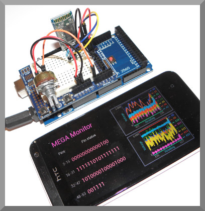
Monitor the analogue and digital inputs of the Arduino Mega on your Android device.
About this demo
The demo uses a Bluetooth HC-06 module to transmit the pin status of the Arduino Mega to an Android device. The android device needs to be Bluetooth capable and have keuwlsoft's Bluetooth Electronics app installed.
Digital pins 0 (RX) and 1 (TX) on the Arduino Mega are used for the serial communication. The status of pins 2-53 are shown as 1s or 0s in one of four binary numbers. The voltage on analogue pins A0 to A15 are shown on the rolling graphs.
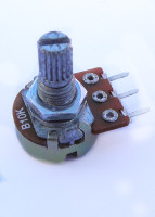
To check the analogue input in this demo, one of the analogue pins is connected to the middle pin of a 10k potentiometer.
Whilst we are using pins 0 (RX) and 1 (TX) for serial communication, the Arduino Mega has 3 other serial channels which could be used instead if the Arduino code is modified.
When running this project, you may find that the graphs are confusing with too much data. Unless you tie the inputs (digital & analogue) to ground that are not being used, you will probably find them fluctuating. An alternative way to tidy things up is to modify the panel in the app and remove all the data channels not used from the graphs/digital indicators.
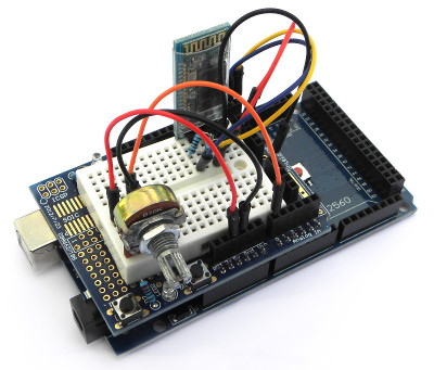
Mega monitor build.
Components used
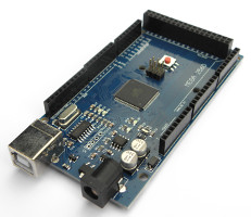
- Arduino Mega
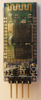
- HC-06 Bluetooth Module
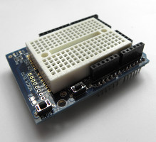
- Prototype Shield
- 10k Potentiometer
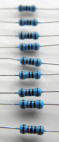
- 10k and 20k Resistors
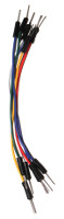
- Some Cables
Circuit Diagram
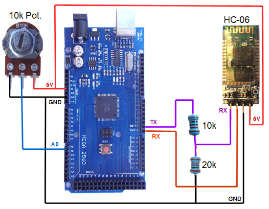
The Bluetooth module has 4 connections, GND, 5V, RX and TX. The TX pin on the Bluetooth module connects to the RX pin on the Arduino and visa versa. For serial communication, a transmit (TX) connection need to be received by a (RX) connection.
Note that the Bluetooth module operates at 3.3V. Supplying a 5V to the Bluetooth RX pin could damage it, such that a voltage divider should be used to supply a 3.3V signal to the RX pin. This is achieved in this demo with a 20k and 10k resistor. The TX pin of the Bluetooth module does not need modification and can connect directly to the Arduino RX pin. This is because the HIGH on 3.3V logic will still be recognised as a HIGH on the 5V logic circuitry on the Arduino.
Arduino code
// Mega Monitor Via Bluetooth
// By keuwlsoft:  www.keuwl.com  26th Sept 2015
// cc Attribution-ShareAlike

// This sketch monitors the Analogue and Digital Inputs and sends
// the results via Bluetooth to keuwlsofts 'Bluetooth Electronics' app.
// Digital Pins 0 and 1 for serial commincation, Pins 2-53 Monitored.
// Analogue pins 0-7 of Graph 1, Pins 8-15 on Graph 2.

int interval=100; //Gives the serial link and app a chance to process data
float voltage; //Assumes 0-1023 range over 5V

void setup() {
 //Initiate Digital pins as Inputs
  for(int i=2;i<=53;i++) pinMode(i, INPUT);

 //Initiate Serial for Bluetooth Communication
  Serial.begin(9600);
}

void loop() {

  //Read Digital Pins and Send results over Bluetooth
    String str="*A"; //Receive char 'A' in app for pins 2 to 15;
    for(int i=2;i<=15;i++) str+=String(digitalRead(i));
    Serial.print(str+"*");

    str="*B"; //Receive char 'B' in app for pins 16 to 31;
    for(int i=16;i<=31;i++) str+=String(digitalRead(i));
    Serial.print(str+"*");

    str="*C"; //Receive char 'C' in app for pins 32 to 47;
    for(int i=32;i<=47;i++) str+=String(digitalRead(i));
    Serial.print(str+"*");

    str="*D"; //Receive char 'D' in app for pins 48 to 53;
    for(int i=48;i<=53;i++) str+=String(digitalRead(i));
    Serial.print(str+"*");


  //Read Analogue Pins and Send Results over Bluetooth
    Serial.print("*G"); //using 'G' as Graph 1 receive char in app
    for(int i=0;i<8;i++){
      voltage=analogRead(i)*0.0048828;
      Serial.print(String(voltage)+",");
    }
    Serial.print("*");

    Serial.print("*H");  //using 'H' as Graph 2 receive char in app
    for(int i=8;i<16;i++){
      voltage=analogRead(i)*0.0048828;
      Serial.print(String(voltage)+",");
    }
    Serial.print("*");

  //Pause before taking next measurement
    delay(interval);
}
Programming the Arduino
To program the device, make sure you remove pins 0 and 1 to the Bluetooth module otherwise the Arduino will get confused trying to communicate to two serial devices simultaneously on the same pins. Run the Arduino software, select the correct COM Port and Arduino device in the Tools menu. Copy and paste the above sketch and click upload.
The strings for the graph data sent over Bluetooth begin with “*G” or “*H” depending on which of the two graphs the data is being sent to. This 'receive character' can be set in the Edit screen of the 'Bluetooth Electronics' app. The string is also terminated with a “*” to tell the app where the end of the string is so that it can start processing the command. Inside the strings are 8 comma separated floating point numbers corresponding the the analogue voltage on Pins A0 to A7, or A8 to A15 respectively.
The digital pin status is sent as four separate strings to four text elements on the Mega monitor panel. High is represented with a '1' and Low signal with a '0'. Digital pins 2 to 15 use the 'A' receive character, Pins 15-31 use 'B', Pins 32-47 use 'C' and pins 48-53 use 'D'. There is a lot of information across 52 pins, such that it might be a good exercise to modify the panel and code to only show what's of interest to your project.
Bluetooth Electronics App
1) Run the Bluetooth Electronics app, click edit.
2) Select library and navigate to the 'MEGA Monitor' demo and copy to panel.
3) Now connect to the Bluetooth device. Turn on power to your circuit so that the LED on the Bluetooth module starts flashing. Click connect on the main screen of the app. If not already paired, click on discover and wait for the device to appear in the list below. Select the device (e.g. HC-06) and click on pair. When requested you will need to enter a pin number, which is usually 1234 for these devices. Once paired, the device will appear on the right hand side. Select it and click on connect. Hopefully this was successful, return to the main screen.
4) The run button should be enabled now that we have connected to the Bluetooth device. Click run and test it out.