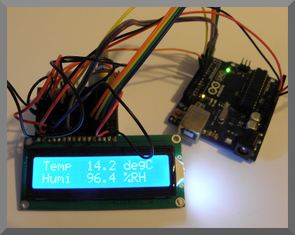
Temperature and Humidity Meter
This example shows you how to communicate with the DHT22
Temperature and Humidity Sensor.
The results are shown on an LCD display and a push button, when pressed will show the
maximum and minimum values on the display. The result can also be sent via the serial connections,
and can be configured to communicate to the Bluetooth Electronics app (optional).
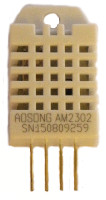
DHT22 Sensor
The DHT22 (also known as AM2302) has a greater range and better resolution that the DHT11 used in an earlier example. The DHT11 is typically encased in blue, the DHT21 in black, and the DHT22 in white. The DHT22 has a temperature range of -40°C to 80°C and a resolution of 0.1°C and accuracy of 0.5°C. The humidity can range from 0 to 100% and has a resolution of 0.1% RH and accuracy of 2%. Resolution is the smallest interval that can be resolved in the measurement, and accuracy is how close to the true value the reading is likely to be.
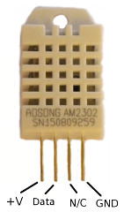
DHT22 Sensor
The DHT22 has four pins, of which only 3 are needed, Looking from the front (the side with a grid of openings) and from left to right the connections are +V, Data, N/C and Ground.
To request a reading from the DHT22, we need to pull the data pin low for at least 1ms (18ms for the DHT11), before raising it and waiting for the response. This is achieved in this example with the code:
  //Trigger reading by holding data pin low for 18ms
    pinMode(DHT22_data_pin, OUTPUT);
    digitalWrite(DHT22_data_pin,LOW);
    delay(18);
    digitalWrite(DHT22_data_pin,HIGH);
    pinMode(DHT22_data_pin, INPUT_PULLUP);
The following pulses are either short (approx. 27μs corresponding to 0) or long (approx. 80μs corresponding to a 1). In total 5 bytes of data are returned.
| Byte 1 | Humidity (Most Significant Byte) |
| Byte 2 | Humidity (Least Significant Byte) |
| Byte 3 | Temperature (Most Significant Byte) |
| Byte 4 | Temperature (Least Significant Byte) |
| Byte 5 | Checksum |
The Checksum is found from the addition of the first 4 bytes (ignoring the overflow into the 9th and 10th bit, only the first 8 bits are used for the checksum). We can do this calculation in the Arduino code and compare with the checksum sent. If they do not match, then we have lost some data in the communication and thus ignore that reading. In reading the temperature from the DHT22, if the most significant temperature bit is a 1, then the temperature is negative.
An example:
00000011 11010001 00000001 01000010 00010111 is returned. The 5 bytes are then:
| Byte 1 (Humidity) | 0 | 0 | 0 | 0 | 0 | 0 | 1 | 1 |
| Byte 2 (Humidity) | 1 | 1 | 0 | 1 | 0 | 0 | 0 | 1 |
| Byte 3 (Temperature) | 0 | 0 | 0 | 0 | 0 | 0 | 0 | 1 |
| Byte 4 (Temperature) | 0 | 1 | 0 | 0 | 0 | 0 | 1 | 0 |
| Byte 5 (Checksum) | 0 | 0 | 0 | 1 | 0 | 1 | 1 | 1 |
Addition of the first 4 bytes: 00000011+11010001+00000001+01000010 = 100010111. The last 8 bits of this answer (00010111) is the checksum.
The humidity is given by (Byte1*256+Byte2)/10. In this example 97.7% RH.
And the temperature is given by (Byte3*256+Byte4)/10 . In this example 32.2°C .
LCD Display
If you are not using a 16 column, 2 row display you will need to modify the code to account for the different size display. If it is larger, just modify the lcd.begin() command. If it is smaller, then the result might not all fit on the display. Note that the LCD display should be compatible with the Hitachi HD44780 driver. The 16 connections for the display are as follows:
| Pin 1 | Ground | Connect to Arduino Ground Pin |
| Pin 2 | Vcc | Connect to +5V |
| Pin 3 | Contrast | Connect to center of 10k Potentiometer |
| Pin 4 | Register Select (RS) | Arduino Pin 7 |
| Pin 5 | Read/Write (R/W) | Only writing, so connect to ground |
| Pin 6 | Enable | Connect to Arduino Pin 6 |
| Pin 7 | D0 | Not Connected |
| Pin 8 | D1 | Not Connected |
| Pin 9 | D2 | Not Connected |
| Pin 10 | D3 | Not Connected |
| Pin 11 | D4 | Connect to Arduino Pin 5 |
| Pin 12 | D5 | Connect to Arduino Pin 4 |
| Pin 13 | D6 | Connect to Arduino Pin 3 |
| Pin 14 | D7 | Connect to Arduino Pin 2 |
| Pin 15 | Back Light +ve | Connect to Arduino +5V Pin |
| Pin 16 | Back Light -ve | Connect to Arduino Ground Pin |
To initialise the LCD display in the Arduino code, we need to specify the 6 digital pins to used with the command:
LiquidCrystal lcd(RS, Enable, D4, D5, D6, D7);Using the pins in this example, this becomes:
LiquidCrystal lcd(7, 6, 5, 4, 3, 2);If no LED backlight is present on your display, there is no need to connect pins 15 and 16. Pin 5 (R/S) determines is we want to read or write to the display. We could wire this to a digital pin on the Arduino to allow us to select the mode, but since we only require to write to the display, we can connect this directly to ground. The power to the display is on pins 1 and 2. Pin 3 selects the contrast of the display depending on the voltage at the pin. The 10k potentiometer is used to adjust the voltage at this pin, and hence also the contrast. The voltage range where text is visible might be quite small, so make sure you include this potentiometer/trimmer and remember to adjust it otherwise you might be wondering why no text is appearing on the display. Whilst it is possible to use 8 data connections, only 4 are required; D4 through D7, which in this example we have connected to Arduino Pins 2 through 5 in reverse.
Push Switch
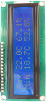
The push switch used in this example changes the state of one of the digital pins such that the code will select different contents for the 1602 LCD display. In this example pressing the button causes the maximum and minimum temperature and humidity to be shown on the lcd display.
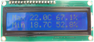
LCD display when button pressed
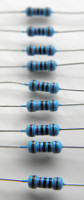
To create a button/switch for the Arduino using a digital input pin, we need a way to change the state of the pin when the switch is pressed, yet it must return to the other state when released. The simplest way to do this is with a pull-up or pull-down resistor which holds the digital input either high or low when the switch is open. When the switch is closed, the voltage at the digital input side of the switch will drop or rise to the opposite power rail.
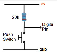
Push switch and pull up resistor
Lets consider an example, with the resistor on the +ve side of the switch and the digital input pin connected to the midpoint as in the above circuit. When the switch is open the voltage will be at (or very close to) the positive rail (5V in this case), and thus the digital input will be a '1'. If the switch is closed, we effectively have a voltage divider with almost zero ohms on the switch size and 20k on the resistor side. The outcome is that the digital input voltage becomes zero (or very close to it) such that the digital input will be a '0'. This position of resistor and switch could be reversed such that the input is normally low and then goes high when the switch is pressed. The value of the resistance is chosen not to be too low such to power is wasted, or too high such that the input signal is noisy/unreliable. 10k or 20k is a typically a good choice for pull-up resistor.
Since the Arduino ATmega processors have internal pull up resistors (typically 20kΩ) we have configured the processor to use these instead by adding the extra line of code:
pinMode(switch_pin, INPUT_PULLUP);
If the internal pull up resistor is used, then only a switch to connect the digital pin to ground is required.
When a switch is pressed, it may not make a clean transition from one state to the other. In most cases it will bounce between the two states momentarily as it is pressed/released. Depending on the code, this could cause unexpected results. To avoid this, the code could be adjusted to ignore transitions for a set interval after the first change of state. Adding a capacitor across the switch can remove the mechanical bounce by causing the voltage at the digital input pin to rise or fall much more slowly dependent on the RC time constant. However this slow transition also causes a prolonged time inbetween the voltages required for each state resulting in unpredictable bounce during this time. To avoid this unstable region, a Schmitt trigger can be used. Therefore adding a capacitor and Schmitt trigger to the switch circuitry can prevent switch bounce. A debounce mechanism is not needed in this example, but otherwise a software debounce mechanism is probably easiest to implement.
Components used
- Arduino Uno
- DHT22 Temperature and Humidity Sensor
- LCD Display
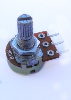
- 10k Potentiometer
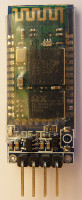
- Optional: HC-06 Bluetooth Module, 10k and 20k Resistors
- Breadboard and some Cables
Circuit Diagram
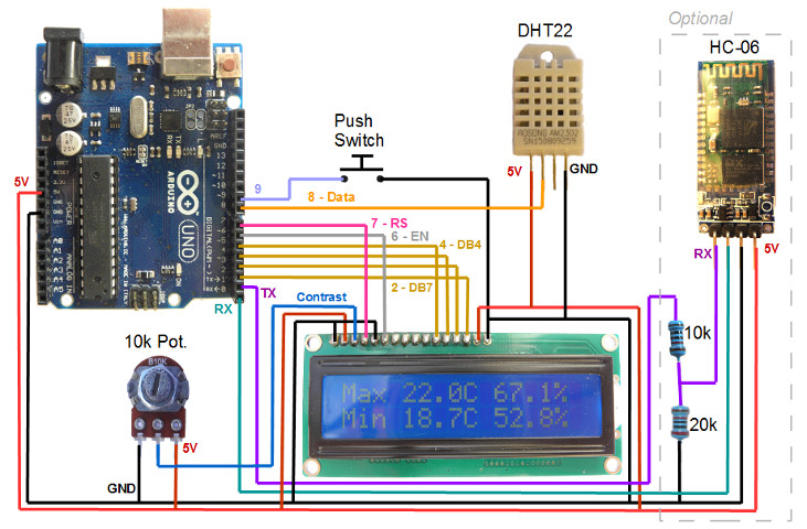
Whilst we are using an Arduino Uno for this demo, you could use a different model or change the connection pins if you prefer, not forgetting to make appropriate adjustments to the code.
If using the HC-06, this Bluetooth module has 4 connections, GND, 5V, RX and TX. The TX pin on the Bluetooth module connects to the RX pin on the Arduino and visa versa. For serial communication, a transmit (TX) connection need to be received by a (RX) connection. Note that the Bluetooth module operates at 3.3V. Supplying a 5V to the Bluetooth RX pin could damage it, such that a voltage divider should be used to supply a 3.3V signal to the RX pin. This is achieved in this demo with 20k and 10k resistors. The TX pin of the Bluetooth module does not need modification and can connect directly to the Arduino RX pin. This is because the HIGH on 3.3V logic will still be recognised as a HIGH on the 5V logic circuitry on the Arduino.
Arduino code
// DHT22 Temperature and Humidity Sensor
// Result shown on a 16 by 2 LCD Display
// By keuwlsoft:  www.keuwl.com  12th July 2016
// cc Attribution-ShareAlike

// The DHT22 returns 5 bytes of data:
// Bytes 1 & 2 are Humidity, Bytes 3 & 4 are Temperature
// Byte 5 is the Checksum

// A switch, when pressed will show max and min values
// Internal 20k pullup on Arduino used for switch

#include <LiquidCrystal.h>
LiquidCrystal lcd(7, 6, 5, 4, 3, 2); //Digital pins used for the LCD

int switch_pin = 9;
int DHT22_data_pin = 8;

boolean result[41]; //holds the result from reading the DHT22
unsigned int databytes[5]; // result converted into 5 bytes
unsigned int checksum;
int interval=500; // Delay between readings
float temp; //Temperature in degrees Celcius
float humidity; //Humidity in %RH
float max_temp,min_temp,last_temp;
float max_humidity,min_humidity,last_humidity;
boolean firstmeasurement=true; //flag used to set max and min on first measurement

void setup() {
  //Initialise Switch Pin to use the internal 20k Pullup resistor
    pinMode(switch_pin, INPUT_PULLUP);

  //Initialise LCD Display
    lcd.begin(16, 2);
    lcd.print("Starting ...");

  //Initiate Serial for Communication (Optional)
    Serial.begin(9600);
}

void loop() {
  //Pause before taking measurement
    delay(interval);

  //Trigger reading by holding data pin low for 18ms
    pinMode(DHT22_data_pin, OUTPUT);
    digitalWrite(DHT22_data_pin,LOW);
    delay(18);
    digitalWrite(DHT22_data_pin,HIGH);
    pinMode(DHT22_data_pin, INPUT_PULLUP);

  //read 41 bits of signal
    for(int i=0;i<=40;i++){
      result[i]=(pulseIn(DHT22_data_pin, HIGH)>40);
    }

  //Convert result to bytes
    for (int j=0;j<5;j++){
      databytes[j]=0;
      for (int i=1;i<=8;i++){
        databytes[j]=databytes[j]<<1;
        if (result[j*8+i]) databytes[j]|=1;
      }
    }

  //Calculate Checksum
    checksum=0;
    for (int j=0;j<4;j++) checksum+=databytes[j];
    checksum&=0x00FF; //ignore exverything except lowest 8 bits

  //Check Checksum
    if (checksum!=databytes[4]){ //Checksum Not Valid
      Serial.print("Bad Checksum"); //Optional
    }else{ //Checksum Valid -> We can Extract and Update ...

      //Extract Temperature and Humidity
      humidity=(databytes[0]*256+databytes[1])/(float)10;  //Extract Humidity
      temp=((databytes[2]&0x7F)*256+databytes[3])/(float)10; //Extract Temperature
      if ((databytes[2]&0x80)>0) temp=-temp;   //MSB of Temperature gives it sign

      //Maximums and Minimums
      if (firstmeasurement){ //If first measurement, also set max and min
        max_temp=min_temp=temp;
        max_humidity=min_humidity=humidity;
        firstmeasurement=false;
      }else{
         if (temp>max_temp) max_temp=temp;
         if (temp<min_temp) min_temp=temp;
         if (humidity>max_humidity) max_humidity=humidity;
         if (humidity<min_humidity) min_humidity=humidity;
      }

      //Write Result to Serial Communication (Optional)
      Serial.print("*T"+String(temp,1)+"*H"+String(humidity,1)+"*");

      //Write Result to LCD
      if (digitalRead(switch_pin)){
        if (last_temp!=temp || last_humidity!=humidity){ //only update if reading changed
          lcd.clear();
          lcd.print("Temp  "+String(temp,1)+" degC");
          lcd.setCursor(0, 1);
          lcd.print("Humi  "+String(humidity,1)+" %RH");
          last_temp=temp;
          last_humidity=humidity;
        }
      }else{
        lcd.clear();
        lcd.print("Max "+String(max_temp,1)+"C "+String(max_humidity,1)+"%");
        lcd.setCursor(0, 1);
        lcd.print("Min "+String(min_temp,1)+"C "+String(min_humidity,1)+"%");
        last_humidity=-1;
      }
    }

}
Programming
Open the Arduino software, select the correct COM Port and Arduino device in the Tools menu, copy and paste the sketch and click upload. If you have connected a Bluetooth module in the circuit, the device, make sure you remove pins 0 and 1 connecting to the Bluetooth module otherwise the Arduino will get confused trying to communicate to two serial devices simultaneously on the same pins. Re-connect them after programming.
Linking to the Bluetooth Electronics App
You may have noticed several serial communication commands in the code. These 4 extra lines of code will cause the data to be sent over the RX and TX pins. Therefore the data can be sent over this link back to a computer (e.g. with the Arduino Serial monitor), or alternatively connected to a Bluetooth module and sent to an Android device. We decided to do the latter and connected an HC-06 Bluetooth module to the power, RX and TX pins. A 10k and 20k resistor were used as a voltage divider such that the HC-06 module only sees 3.3V logic on its RX input and is not damaged. The above Arduino code as it is will communicate nicely to the temperature and humidity demo panel in the Bluetooth Electronics app. In this case we added a couple of graphs to the panel to show the recent history of temperature and humidity. This can be achieved by editing the panel in the app, selecting graph and dragging a roll 3x2 graph onto the panel, and then editing it as required making sure the receive characters match those sent by the Arduino (i.e. 'T' for Temperature and 'H' for Humidity).
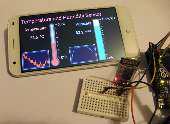
Using Bluetooth to show the results on an Android device
To use the app with this example, follow these steps:
1) Run the Bluetooth Electronics app
2) Select library and find the temperature and humidity demo panel.
3) Select graph and drag some onto the panel if required, not forgetting to click edit and adjust their properties as necessary.
4) Connect Bluetooth: Turn on power to your circuit so that the LED on the Bluetooth module starts flashing. Click connect on the main screen of the app. If not already paired, click on discover and wait for the device to appear in the list below. Select the device (e.g. HC-06) and click on pair. When requested you will need to enter a pin number, which is usually 1234 for these devices. Once paired, the device will appear on the right hand side. Select it and click on connect. Hopefully this was successful, return to the main screen.
5) The run button should be enabled. Click run and test it out.